Gather at the center
A properly designed fire ring belongs in the middle of the main social terrace, with a clear circulation zone around it and tents kept outside the fire area.
Family basecamp · Prototype 01 · Fourth of July 2026
A working prototype for a permanent hilltop campsite with a deliberately temporary streak of chaos: four overlapping slide segments, roughly 110 feet of downhill run, and a water castle recessed into the backyard landing.
The site
The social terrace sits on the elevated hill southwest of the house, beyond the backyard. The fire ring anchors the gathering area; an approximately 15-foot retained path climbs southwest to the primary campsite, secondary camping sits immediately east of the social terrace, and the slide takes a direct northbound line down to the backyard.
A properly designed fire ring belongs in the middle of the main social terrace, with a clear circulation zone around it and tents kept outside the fire area.
An 8-foot-wide path runs approximately 15 feet southwest and uphill from the social terrace, with a retaining wall on each side. It reaches the primary campsite, where the north-facing water view is strongest; secondary camping remains immediately east of the social area.
The slide corridor runs straight north and downhill from the social area to the backyard, keeping the path readable, the joints aligned, and the landing visible from above.
Selected landing
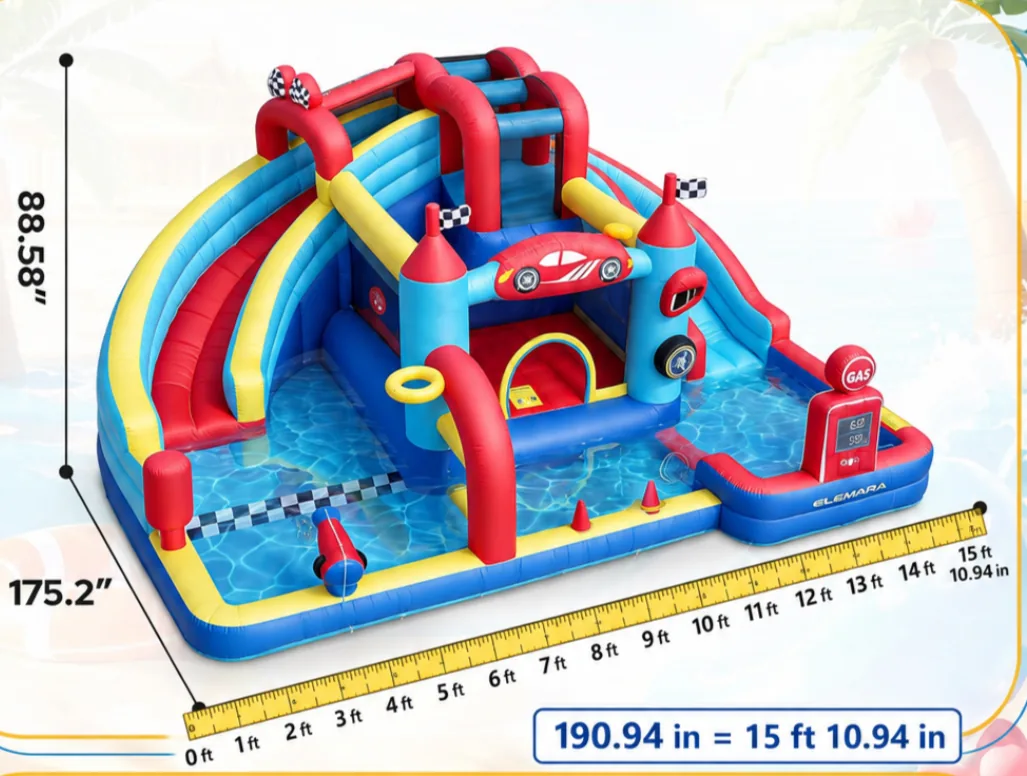
The race-car water castle is approximately 15 ft 11 in wide when facing it, 14 ft 7 in long front to back, and 7 ft 5 in high. Its broad front basin serves as both impact area and water reservoir for the recirculation loop.
With adult spotters controlling the landing, younger kids enjoy the castle’s opposite play side while older kids and adults come smashing into the slide-facing basin.
Slide + water system
The thin slide plastic is the wet riding surface, not the anchor. Moving blankets distribute load and add friction against the graded trail; stakes limit lateral drift. Water returns through the recessed castle basin and is relayed uphill by three transfer pumps.
Four commodity segments—32 feet each before overlap—are shingled together to create an approximate 110-foot run. Standard and heavy-duty moving blankets sit beneath the plastic to cushion rocks and resist downhill movement.
Stake role: alignment only. Any major downhill load transferred to the stake holes can tear the slide.
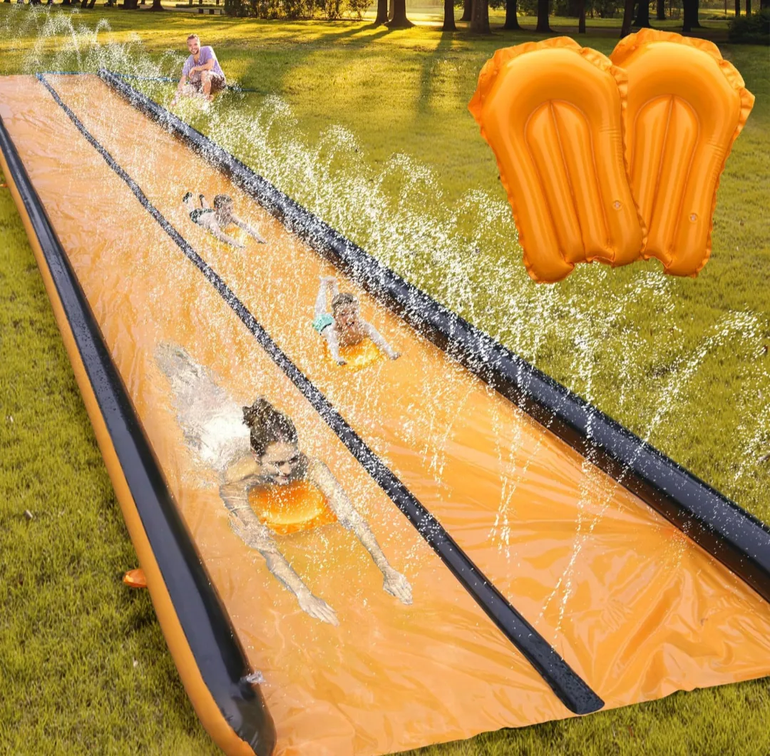
The four plastic segments and their inflatable bumpers together measure just under 6 feet wide. The flexible bumpers can roll outward when pressed, so the wider 9–10-foot prepared corridor provides necessary clearance. Segment overlaps point downhill so riders and water cross each seam in the shingled direction.
Closed loop
Around Pump 1: filtered basin water enters one manually valved Y branch; the other receives a separate priming hose through its own manual valve. The common Y outlet feeds Pump 1. A check valve mounted directly on the pump outlet stops the long uphill relay line from draining backward through Pump 1. With an airtight intake, that preserves the discharge-side water column and reduces the need to reprime between starts; initial startup still requires a filled pump housing and suction path.
Water rides the full slide and returns across the landing transition to the castle basin.
Critical interface
The castle is recessed so its basin lip sits below the incoming slide. A 6-foot-wide roll of foam was pared down by unrolling and discarding the excess until the remaining roll was the right diameter, then tucked beneath the final slide segment to make its bend into the basin more gradual. The flexible end hangs slightly downward into the basin, giving water a continuous downhill path with no uphill seam or exposed pocket.
Build log
The excavation established the route. Finish grading refined the landing. The final installation added underlayment, four slide segments, water delivery, and power planning.
Major excavation
The excavator formed the primary campsite and cleared the 9–10-foot-wide slide path from the hill to the backyard before handling several unrelated small projects elsewhere on the property.
Fit + finish
Excavation touchups cleaned the corridor, then hand raking and rock removal prepared the riding line. At the bottom, the hill was dug back so the bounce castle could sit below the incoming slide and collect the return water.
Full installation
The underlayment went down first. The castle was set into the lowered landing, followed by all four slide sections, and the three-pump water relay and separate AC routing were laid out.
Field test
The first test and the runs that followed proved the full route—from the upper launch, over four overlapping slide sections, and into the recessed castle landing.
Multiple riders and camera positions show the upper launch, four overlapping slide segments, recessed castle landing, and working return-water concept as one continuous course.
Operating note
Before each session, inspect seams, blanket movement, exposed stakes, landing depth, hose connections, pump instructions, and outdoor GFCI protection. Use adult spotters at both ends, send one rider at a time feet-first, and stop immediately if the landing, water return, or slide alignment changes.